
Configuration file for data acquisition server
In order to run Aqserver you need a configuration file where all required parameters for a acquisition from a S7PLC are stored. When Aqserver is starting, this configuration is scanned, the parameters a re checked for correctness, then the acquisition starts.
Prerequisites
Multiline settings must be indented with TAB, see “remarks”
In config file comments start with a “#”: “#” at 1st column of line will be a comment, you can also use it to disable settings. Note that always one valid setting must be available
Use ”;” for inline comments
Multiline comments must be indented with TAB, see “remarks”: If you want to have some text in more than one line, following lines must be indented with TAB, see remarks in aqdata settings
Settings in config file
Aqdata settings
For information purposes, we can set some texts, that will be included in the data file header. You can add a text by placing the name starting in the first column followed by a “=” and the text you wish to be implemented.
Note
Also all config values are included in the datafile. When you open an de-archived datafile, you can copy these to make the same config file, if you have lost the original one.
########################################################################
# aqdata settings
########################################################################
[aqdata]
place = somewhere

creator = Michael Taxis

machine = MyMachine

order = 123456

yourText = type whatever you desire

remarks = ; use tab for multiline values
    trials with double spreader, to get rid of married rolls
    trials for SF production
Communication settings
For communication with S7 we need following parameters:
- demo: aqserver can run in demo mode, values are created randomly, without communicating to a plc
- IP address: IP address of the PLC you try to reach. Try a PING before you start!
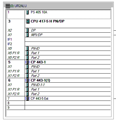
- rack number: normally is 0
- slot number: normally is number left of CPU in HW configuration, in example in picture below it is 3.
- maximum connection attempts: Program tries to connect to PLC. If it fails after this number of trials/attempts the program stops. Then check your configuration and connection. If the value is set to 0 the program will try forever. This can be useful if you have the program running without supervision. If not sucessful you can still stop it with CTRL-C. When communication is interrupted/disconnected during a recording session, it will try to reconnect. There will be no recording of values when disconnected.
########################################################################
# communication settings
########################################################################
[communication]

# setting up communication parameters to S7-PLC
# demo switch
# if 1 communication will be ignored and values will be randomly created
# if 0 then aqserver tries to connect to a plc
demo = 0


# IP address
# you can leave several settings , just comment with a leading "#"
#ip = 192.168.1.107
ip = 172.16.13.174

# rack number, see HW Config
rack = 0

# slot number of CPU, see HW Config
slot = 3

# maximum attempts for connection, 0 is trying forever
maxattempts = 10
Note
You can also try Aqserver with PLCSIM and NetToPlcsim from http://nettoplcsim.sourceforge.net/ on the same machine.
Miscellaneous settings
We need some general settings for aqserver, as follows:
delimiter: is the character that separates the recorded values in the data file, normally we use ”;”. Be careful not to use the decimal separator that is used on your system (so don’t use ‘.’ or ‘,’)!
datafileprefix: here we can define a name, that is used to identify the data file. It is a prefix, because file name also includes a timestamp e.g.: MyProject20150804_173035.csv.gz
datafile is the filename, without extension, where actual data are recorded. This is a csv-file. If you intend to run multiple instances of the program, in order to reach different PLCs, make sure that this name is different in all config files!
autostart: defines whether recording is starting with program start, or is waiting for a start signal
datapath: here we define were the compressed data files will be stored.
usedir: defines, whether we use a directory structure as \yyyy\MM\dd\ when storing the archived files.
scantime: scantime in milliseconds[ms], minimum is limited to 20 ms in program. This time is only an approximation, because it also depends on number of variables to scan, but use it to reduce filesize. The more scans the bigger the file. If you set scantime to 0, the program will read the data as fast as possible (Attention: big data file!). Depending on the number of values scantime of ~10 ms can be reached.
maxrecords: This number defines the maximum number of records stored to one file. This limit the size of a datafile. Depending on the number of values per record you should check what number is applicable for you.
- booloffset: set this to 1 and the bit in one byte will be offset by 2 as follows:
value + bit number * 2
With this the bits can be shown in Kst within one plot without overlapping each other
bit true false 0 1 0 1 3 2 2 5 4 3 7 6 4 9 8 5 11 10 6 13 12 7 15 14 if booloffset is 0 then only the boolean value (1 for true, 0 for false) will be stored.
########################################################################
# miscellaneous settings
########################################################################
[misc]

# miscellaneous values for setting up the acquisition server
# value delimiter in storage file
delimiter = ;

# prefix of data file name, e.g. a customer/project name or whatever
datafileprefix = MyProject

# data file name for actual data recording, without extension!
# e.g. if you use "filename", actual name will be "filename.csv"
datafile = recording

# autostart: when program is started decide whether acquisition is started(1)
# immediately or wait for start signal (0)
autostart = 0

# path for data files, use "\" for directory separation, with "\" at the end !
# e.g. datapath = D:\mydata\
datapath = F:\aqdata\MyProject\

# if 1 use directory structure datapath\yyyyy\MM\dd otherwise use only datapath
usedir = 1

# scantime in milliseconds [ms]
# if you just put 0 program will scan as fast as possible
# this will produce rather large data files!
# depending on number of values this value is just a hint ;-)
scantime = 100

# maximum number of records
# to avoid too big data files, a new one will be starfted after this number
# of recordings
maxrecords = 50000

# switch for offset of boolean values
# if 1 then boolean values in a byte (see values settings) will be offset by 2 as follows:
#
# value + bit number * 2
#
#  bit | true | false
#  ----+------+-------
#   0  |  1   +  0
#  ----+------+-------
#   1  |  3   +  2
#  ----+------+-------
#   2  |  5   +  4
#  ----+------+-------
#   3  |  7   +  6
#  ----+------+-------
#   4  |  9   +  8
#  ----+------+-------
#   5  | 11   + 10
#  ----+------+-------
#   6  | 13   + 12
#  ----+------+-------
#   7  | 15   + 14
# if booloffset is 0 then only the boolean value (1 for true, 0 for false) will be stored
booloffset = 1
Trigger settings
Trigger settings are used to start a new datafile, when a trigger event occurs. A trigger can also be raised manually by pressing key ‘t’ on your keyboard! This trigger event is defined by the following three trigger settings:
- trgsignal: This is the “name” of the signal from the value section, that will trigger the event. Copy the name from the value section.
- trgcondition: This the condition for a comparison of the triggersignal with the trigger value. E.g. when the condition is “==” then the trigger will be raised, when value of trigger signal and trigger value match
- trgvalue: This is a constant, trgsignal is compared with it, to decide about the trigger event.
Further 2 values are used to overlap old and new file:
- pretrg: time that will be recorded to new file BEFORE the trigger in [s]. This is based on setting scantime.
- posttrg: time that will be recorded to old file AFTER the trigger in [s]. This is based on setting scantime.
########################################################################
# trigger settings
########################################################################
# when trigger condition is matched, then we close the old file after
# post-trigger time and start the new file and copy pre-trigger time
# and post-trigger recordings to new file
#    # condition is, with example:
# trgsignal trgcondition trgvalue
# rewind diameter [mm] = 0
#
[trigger]

# trigger signal, copy the name of the signal in [values] section,
# that you want to use as trigger signal
trgsignal = rewind diameter [mm]

# trigger condition, use >,>=,==, <=,<,!= as condition
# when conditon is matched, then we close the old file and start a new one
# trgcondition = >
# trgcondition = >=
# trgcondition = ==
trgcondition = <=
# trgcondition = <
# trgcondition = !=

# trigger value, with this value we compare the trigger signal
trgvalue = 0

# pre-trigger time in seconds [s]
# will still add pre-trigger/scantime lines to old file after trigger event
# e.g. pre-trigger is 60 seconds and scantime is 100 ms, then 600 lines
# will be recorded after trigger event
pretrg = 30

#post-trigger time in seconds [s]
# will copy last post-trigger/scantime lines from old to new file
# e.g. post-trigger is 60 seconds and scantime is 100 ms, then 600 lines will
# be copied after trigger event
posttrg = 30
Debug settings
The debug settings define whether and how we do some logging to debug the program.
For debugging we have to define a debug level, that defines what will be logged.
With level “0” we switch off logging completely, with level “1” everything will be logged Note that when you restart the program the log directory will be purged,leaving only the latest log-file
Parameter logfile defines the name of the logfile, without extension. Extension will always be ”.log”
If parameter logts is 1 everytime we start the program a new log file will be created. If logts is 0 then we will always append to the default log file.
########################################################################
# debug settings
########################################################################
[debug]

# debug level
# set logging level to debug, write program actions
# to logfile
# 0 - no logging
# 1 - log INFO messages (default setting)
# 2 - log WARNING messages
# 3 - log DEBUG messages
# 4 - log ERROR messages
# 5 - log CRITICAL messages
# 6 - log EXCEPTION messages
dbglevel = 2

# name of logfile, without extension. Extension will be added as ".log"
logfile = aqserver

# add timestamp to logfile name 1 = yes, 0 = no
# if set to 1 a timestamp will be added to the lofile name. pls. note that a
# new logfile will be created, every time you start the server,
# when dbglevel is > 0
logts = 1
Value settings
In the config section values, we can list our PLC variables we want to read. A value definition consists of the name followed by an equal sign and the address of the variable to be read. In the name the unit of the value can be implemented in rectangular brackets []. The unit will be extracted from the name and written in an extra line in the datafile.
The definition of the address does not follow the S7 syntax, because our syntax includes the address, the format (bool, int, float) and the size of the variable in bytes (bool, byte, word, double word) in one parameter. Syntax is described in detail below.
Defining boolean values is a littlebit special, because we always read at least one byte from the PLC. Therefore we split this byte in 8 single booleans. To define which boolean out of 8 we want to record, we have to split the names of the single booleans with a ”,”.
If we omit text between commas, then this bool will be read but not recorded to the datafile.
See the following examples, where we compare S7 syntax with our definition syntax:
| PLC syntax | Format | our definition |
|---|---|---|
| DB4615.DBD714 | REAL | DB4615.DF714 |
| ED 4 | DINT | ED4 |
| AW 4 | INT | AW 4 |
| DB4615.DBB6 | INT | DB4615.DB6 |
| DB4615.DBX6.1 | BOOL | DB4615.DX6 (byte!) |
########################################################################
# value settings
########################################################################
# here we define the S7 variables we want to read, and their formats
# here we define the S7 variables that we want to observe
# use following syntax:
#
######### how to define the names: ########################################
# use config value name with [ ] - brackets to define the unit of the value
# units will be separated from the name and put into the datafile
#
# boolean values:
# For boolean values (see format X above) a complete byte is read and then
# split into 8 bits
# To define names for the single bits use ',' to separate the names, e.g.:
#
# bit0,bit1,bit2,bit3,bit4,bit5,bit6,bit7 = DB1234.DX5
# Ventil 1, Ventil 2, Ventil 3, Ventil 4, Res1, Res2, Res3, Res4 = DB1234.DX5
#
# If you do not want all the bits, leave the name empty e.g.:
#
# bit0,,bit2,,,,, = DB1234.DX5
#
# This reads only bit0 and bit2
#
#
######### how to define the values: ############################################
# (S7 variable and format)
# DBn.AFn.x
#
# where:
# - DB is for data blocks or omitted if other area
# - n is DB number or omitted if other area
#
# - . only when data, omitted otherwise
#
# - A is area
#   - D for data
#   - M or F for flags
#   - E or I for inputs
#   - A or Q for outputs
#   - T for timers
#   - Z or C for counters
#
# - F is format:
#
#   - X - for BYTE in BOOL format, followed by byte address:
#   - n is whole number for byte address
#     (attention to address ranges of PLC)
#     will always be split in 8 single booleans
#
#   - B - for BYTE in int format, followed by byte address
#   - n is whole number for byte address
#   (attention to address ranges of PLC)
#
#   - W - for WORD, followed by byte address
#   - n is whole number for byte address
#   (attention to address ranges of PLC)
#
#   - D - for DOUBLE WORD, followed by byte address
#   - n is whole number for byte address
#   (attention to address ranges of PLC)
#
#   - F - for DOUBLE WORD in REAL format, followed by byte address
#   - n is whole number for byte address
#   (attention to address ranges of PLC)
#
#
[values]
rewind diameter [mm] = DB4615.DF714
webspeed actual [m/min] = DB4615.DF574
vibration left core chuck [mm/s] = DB4614.DF560
vibration right core chuck [mm/s] = DB4614.DF564
vibration rider roll [mm/s] = DB4614.DF568
#Klemmventil UM1,Klemmventil UM2,Klemmventil UM3,Klemmventil UM4,,,, = DB4614.DX564